
|

|
|
|
Christopher's Web Site
|
Date: 12-4-2015
|
Number of Hours: 6.00
|
Manual Reference:
|
Brief Description: Engine Conversion Stand
|
|
Before finishing the instrument panel, I decided to attempt to make the engine stand required for the horizontal to vertical engine conversion process. I took a whole two day MIG welding class back in February, so I think I can safely consider myself a professional welder at this point. (Can you smell the sarcasm?!). I also have never welded with flux core, so this was a new experience all the way around. The only comforting thought is that the engine stand is staying on the ground and I don’t have to worry about my welds while flying.
I bought everything as raw stock and cut the sizes I needed with my metal chop saw based on the one page drawing in the back of the helicopter blue prints. The one page picture was not very descriptive, but good enough to put it together. The assembly required the welding of four pieces of 24” x 1 1/2” angle iron as the base, then four one inch tubes perpendicular as the stand. I welded bolts to washers, then the washer/bolt assembly to the top of the tubes, being careful to reset the welder for power and wire speed with each new material thickness. I think my best weld was “okay”, with the majority of them listed as, “oh jeez…”. From a galloping horse I think it looks fine, and I stood on top of the board I was using for alinement of the engine bolts, and the stand seems solid.
To make it a bit more flexible in the shop, I also added locking wheels which seem to be recommended by many of the other builders online. I don’t expect my engine until February, but I wanted to check this off my list so I would be ready to go once it arrived.
|
|
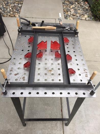
Base clamped in place
|
|
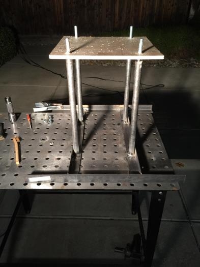
Template for engine mount
|
|
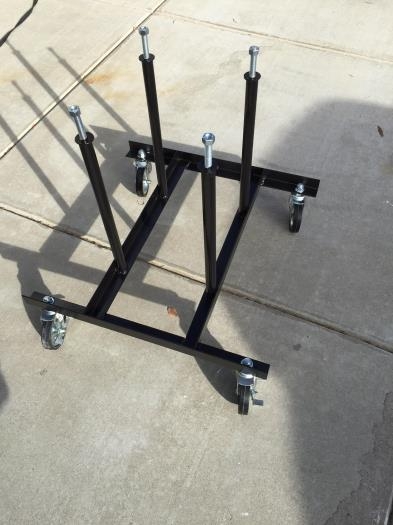
Finished and mobile!
|
|
|
|
|
|
|
|
|
Copyright © 2001-2024 Matronics. All Rights Reserved.
|