Brief Description: Propeller spinner fitting continued
Continued from previous posts:
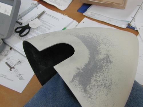
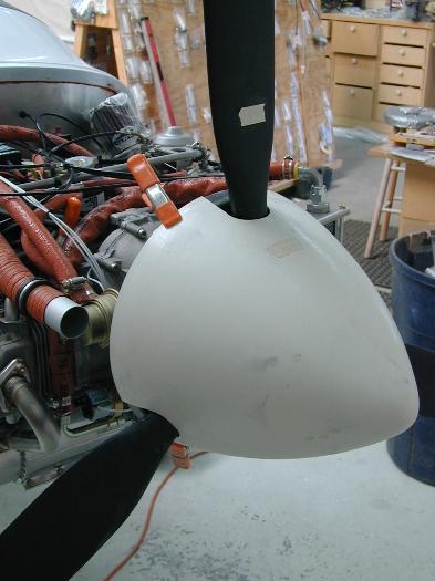
After the propeller unit is installed it is time to fit the spinner unit. This entails laying out the three cutouts to allow the spinner to slide past the blade hubs and over the backing plate.
I laid out the position for the three cutouts, carefully measured the blade hub diameter and the distance from the aft edge of the backing plate to the forward surface of the blade hub, and then made a paper template. I made the template under-sized in height and width planning on sneaking up on the clearance needed to clear the blade hubs. I cut the spinner and sanded to my lines using a dremmel tool (poor mans die-grinder). Through repeated gradual fittings and sanding steps I removed material from the spinner until it cleared all three blades. I also slowly increased the depth of the cutouts until the spinner lined up with the aft edge of the backing plate.
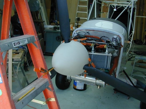
With the spinner clamped into place with a series of spring clamps, I wanted to check the spinner for alignment and "wobble". I was advised to fabricate a precision instrument to carefully check the runout/alignment/wobble. As you can see in the third photo my alignment instrument is a heavy-duty step ladder with a pencil clamped in place and aligned at the tip of the spinner. WIth a spark plug removed from each cylinder I was able to rotate the engine by hand, and with the pencil barely touching the spinner I was able to check the alignment of the spinner. I made a number of trial and error adjustments until I eliminated any wobble/runout.