
|

|
|
|
Jims Web Site
|
Date: 12-8-2009
|
Number of Hours: 2.30
|
Manual Reference: 6B5-2
|
Brief Description: Installed Master power relay
|
|
I spent 1.9 hours designing a sheet metal bracket to mount the battery relay. When I looked at what I designed, and looked at the aircraft, I decided to scrap the idea, and to mount the battery relay on the front face of 6B5-2, the rear frame channel.
1. Checked electrical conductivity between 6B5-2 and aircraft bottom, where battery ground lead will be connected. 6B5-2 has a lot ohmage reading, probably below meter limits. This is necessary, since the relay case provides the ground path for activating the relay.
2. Marked and punched location for mounting holes on 6B5 -2.
3. Drilled pilot holes with #40 bit.
4. Checked relay fit.
5. Opened mounting holes with #8 bit.
6. Mounted relay with #10 screws, 2 flat washers, and lock nuts.
Note: the present plan is to run a suitably sized wire from the relay activation post to a master switch on the front panel, via a fuse. Realy output will go via a #2 wire to the starter relay in the vicinity of the front panel. The starter relay input will also be connected to the master avionics buss.
|
|
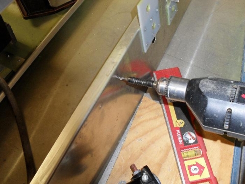
Drilled pilot holes to mount battery relay
|
|
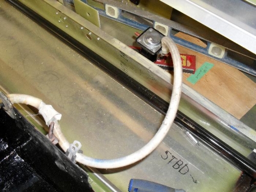
aft view of mounted relay
|
|
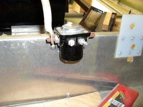
Forward view of mounted relay
|
|
|
|
|
|
|
|
|
Copyright © 2001-2024 Matronics. All Rights Reserved.
|