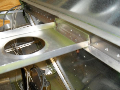
Brief Description: Fit and clecoed support channel
1) Positioned support channel 6K2-1 atop side fairings 6K2-3. 2) Added "L" angles atop side fairings, to attach to support channel. 3) Drilled with #40 bit; opened to #30 for A4 rivets. 4) Cut "L" angle to fit between support channel and center console. 5) Opened angle of "L" channel; with hand seamer. 6) Drilled #40 pilot holes in top of center console. 7) Back drilled into "L" angle; opened to #30 and clecoed. 8) Drilled #40 pilot holes in support channel to attach to "L" angle and avionics panel. 9) Back drilled into "L" angle and avionics panel. 10) Opened holes to #30 and clecoed. 11) Cut piece of .025 6061T6, and bent into longer than usual "L" angle to fit between firewall and support channel. 12) Removed existing A5 rivets in front of "L" angle. 13) Pilot drilled bottom with #40 bit. 14) Opened to #30 and clecoed from bottom. 15) Back drilled end rivet holes on face of "L" angle with #20 bit, and clecoed in place. 16) Sprayed through other rivet holes with black enamel onto fabbed "L" bracket to get positions. Note: Holes were too inaccessable from front to back drill.
All parts were deburred, cleaned, and mating surfaces were primed with zinc chromate before installation. 17) Removed "L" bracket; and drilled #40 holes in center of black paint. 18) Replaced "L" angle, and back drilled with #20- bit