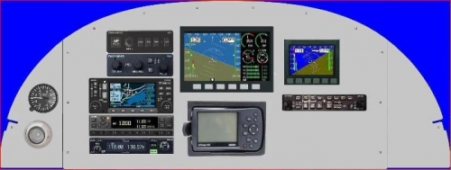
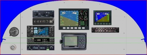
The panel has been finalized and will be cut out soon. I had to move some things around, to have it the way I originally wanted things the G-430W would have interfered with the cross cabin brace. I call the area in the panel that any box longer than 10.5 inches would contact the cross cabin brace the “Brace Zone”, well the ICOM 210 and the Garmin 430W are two such items. One of my photos below shows the rough approximation of the brace zone. I actually like the layout the way it is now. All of the control panels for the Dynon are near my free hand along with the radios; I moved the intercom panel to the right to allow the EFIS/EMS to move down some. This will allow me the option to go to Dynon’s next generation stuff if I want. Of course the D-10A is over to the right, the extra space around it lets me flush mount it, the other side it could not be flush mounted due to the bracket design, it needs like and inch above and below the unit. The ICOM and the transponder were flip flopped since the transponder is shallower than the ICOM. It will still be a tight fit, the Garmin 430W is 11 inches before antenna and wire harness plugs, and there is only 12 inches to play with.
I really should count this to my build time considering how much of my time I have spent in this area the last few weeks. This and the electrical system design have taken a considerable amount of time and effort to work though.