
|

|
|
|
RVGator
|
Date: 6-30-2009
|
Number of Hours: 5.00
|
Manual Reference:
|
Brief Description: Battery cable to the firewall
|
|
Well the battery cable is installed, roughly. I first riveted the battery tray parts together, I still need to rivet the nut plates for the hold down bolts but I need some -3 universal rivets that did not come in my kit. After bolting the mastery relay to the battery tray I installed the tray. I then looked over the routing for the battery cable on the right side, a mirror image from what Van’s instruction show for the left side.
Two reasons I am going up the right, one, I don’t have a lot of room under the left console due to the fuel lines, fuel selector and rudder pedal idler arm. Second the step support is in the way of the hole drilled to run the wire. This is no problem for the tail wheel models but no for the nose wheel models with the step. On the right side I have not problems under the console. I called and asked Van’s about this and they thought it would be fine. I needed to drill on hole in the F-807 bulkhead, the F-804 bulkhead and the exit hole in the firewall. The firewall hole I thought would be tough it being stainless steel, but a step drill run nice a slow with some cutting oil and it turned out nice. I then drilled the holes required for the cushion clamps to hole the cable in place. After this I ran the wire and installed the grommets. I need to decide what kind of firewall pass through I will need to make or buy, I temporarily installed a plastic grommet.
After test fitting the cushion clamps I added some to hole the cable lower, I am concerned the cable will interfere with the aileron push rod, you can see what I mean in one of the photos. A lot of time for one wire but it’s done. A wire to for the tail light and trim servo and I think I will be ready to rivet on the turtle deck.
|
|
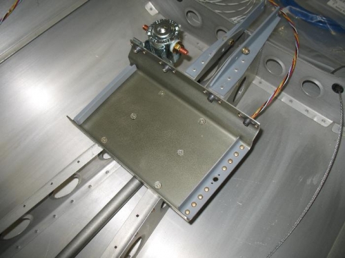
Baterry Tray with master relay attached.
|
|
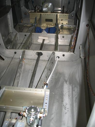
You can see the whiite step support block in the way on the left.
|
|
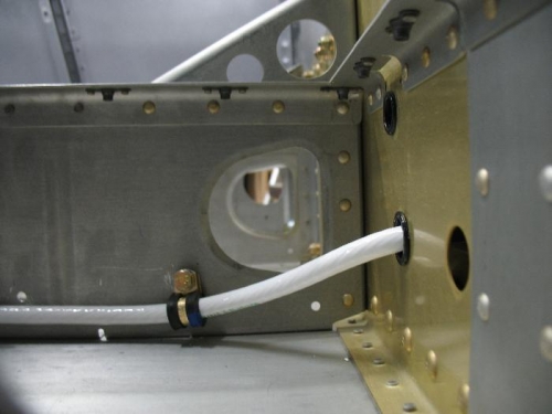
This is shot from the outside, towards the direction of the push rod attachment to the control column
|
|
|
|
|
|
|
|
|
Copyright © 2001-2024 Matronics. All Rights Reserved.
|