Brief Description: Part 2: Aileron stops installed, checked travel li
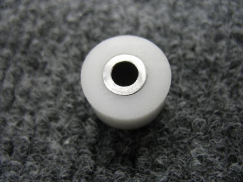
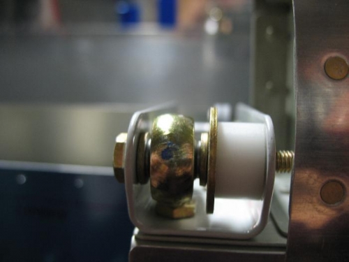
I received my delivery from Spruce which had some 5/8” Delrin (hard nylon) rod I am going to use to make some aileron stops. The plans call for riveting some tabs on the aileron hinge bracket which seems kind of time consuming. I am using an idea many have used which is to take some of this hard nylon rod and cut it to length and drill it out with a 5/16” hole, to accept the aluminum bushing that fits in the area the push rod connects to the aileron. As the aileron moves up this nylon bushing will hit the aileron hinge bracket and thereby limit the upward travel. After fabricating these stops I installed them on the ailerons. Since the left aileron neutral position is already set I tested to see what kind of travel the 5/8” stop will give me. Using my digital level I measure from the neutral point to the upper stop and I get 30 degrees of travel. The plans call for 32 maximum and 25 minimum so I am on the upper edge. The ½ inch rod might give me a little more travel, but since I am well within the limits I will keep these for now. I want to see what kind of down limit I get but I have to wait until the wings are attached to the fuselage. The upper travel limit on one wing will define the down travel limit on the opposite wing, so having 2 degrees from the upper limit now should ensure I do not exceed the down limit.
Bushing from plans surrounded by nylon bushing made from Delrin rod
Installed to aileron hinge
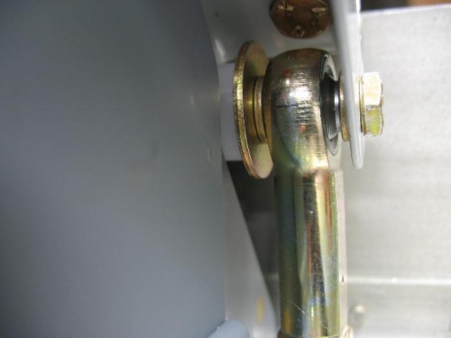
How it contacts the hinge bracket, this is what stops the aileron upward travel.