Brief Description: Part 2 Hose and wire route test
I continued my work on how to route the starter and alternator wire, I hate counting this as build time but heck I have to sit there and what if the different locations, I am not counting the time I stop to go look up something online.
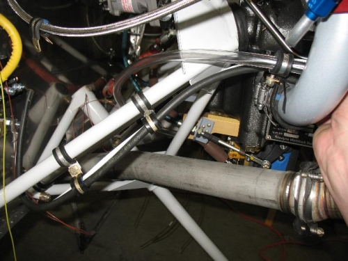
I have about nail down the power wires, I then used a clear hose to simulate the fuel line that will run through here. My engine came with one fuel line that runs from the fuel servo up between cylinders 1 and 3 to the fuel distribution spider. I need to figure out where in the line the fuel flow meter will go.
I decided on suspending the fuel flow sensors between two clamps connected to the two sides of the “V” formed by the engine mount supports. My concern is how much slack to have between supports between the engine mount side and the engine. The engine support clamp is stationary while the engine itself will move on the rubber mounts. I need to run this by someone and get a sanity check.
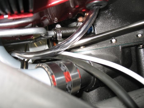
Wires run along support in clamps to...
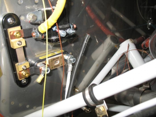
Here t, fat black is starter wire and white is alternator B-lead
Looking aft, alternator wire will brach off here to the alternator.