Brief Description: Main gear booties and bilge through hull
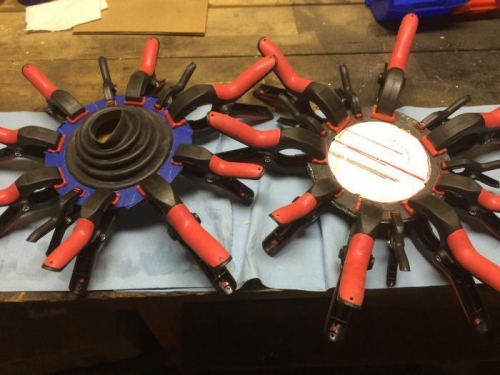
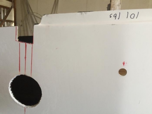
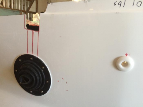
After my abortive attempt earlier to glue the main gear rubber booties to the plastic retaining rings I studied the instructions Section 5 (steps 31 - 35), examined the rather unclear manual photos again and read other builders' logs. I am not so sure that my first attempt was actually wrong! But here I go with attempt #2. As you can see in the photo below, I have put blue masking tape on the textured side of the retaining ring (step 31.3), inserted a supporting disc inside the bootie and inserted the bootie through the ring (step 32), glued the non-taped side of the ring to the bootie and clamped (step 33), ending up with two assemblies that look exactly like the manual photo is step 34. This has to be correct! Correct? After letting the contact cement set up overnight I installed both main gear bootie asemblies into the hull cut-outs using the #10x3/4" SS sheet metal screws supplied. The tips of the screws stick through on the inside of the hull which I want to cover over somehow later in the build. I made sure to caulk around the outside perimeters of the rings. At this time I drilled and reemed out a 1" hole for the bilge pump discharge hose through-hull (step 36). The manual says to locate the hole approximately 6" 'down the side' and 12" aft of the Upper Bulkhead Tube. I placed it exactly 7 1/2" down from the very top edge of the hull to make sure it went through the thickened section of the FRP hull. Don't forget to caulk.
Booties redone
holes for gear bootie and through hull - port side