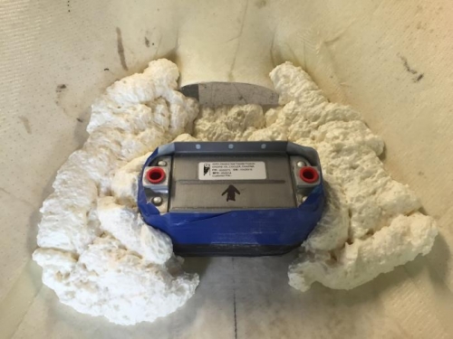
The lower cowl has an inlet under the spinner for oil cooler inlet. The cowl doesn't have any duct work behind the hole. internal ducting improves the pressure recover of the inlet and also seals the inlet against the oil cooler so that no high pressure air escapes into the lower plenum.
I am also taking the engine inlet air, carby heat air and cabin heat are from in front of the oil cooler. My thinking here is that cabin and carby heat air are used when either the engine is NOT at full power or the outside air temp is low. So you don't need as much oil cooling. The primary engine inlet air doesn't fit this thinking as it is maximum when the engine needs the mmost oil cooling.
Doing some analysis of the inlet it seems like there is plenty of pressure available in front of the oil cooler. So my thinking is that sharing this inlet is not a problem for oil cooling. his inlet will provide more pressure to the induction system than using the normal side mounted NACA duct. So I am really trying to get more manifold pressure from this design.
I also expect the ducting behind the oil cooler to enhance oil cooler flow above the normal method of letting it out into the lower plenum without a diffuser.
Hopefully this works OK.
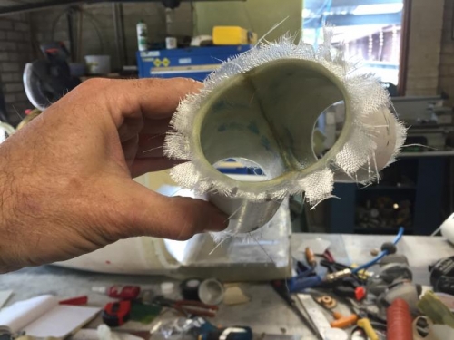
Forming the diffuser duct for the oil cooler inlet.
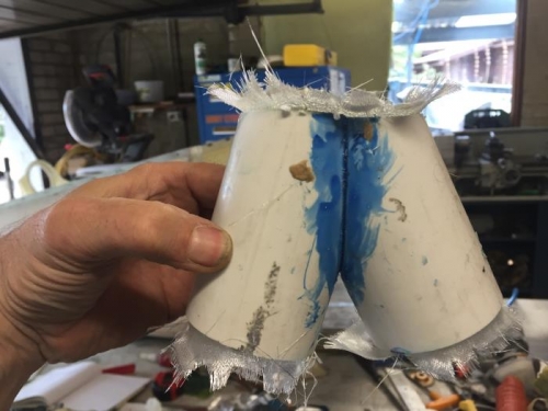
the twin outlet providing air to teh engine inlet. One via carby heater.