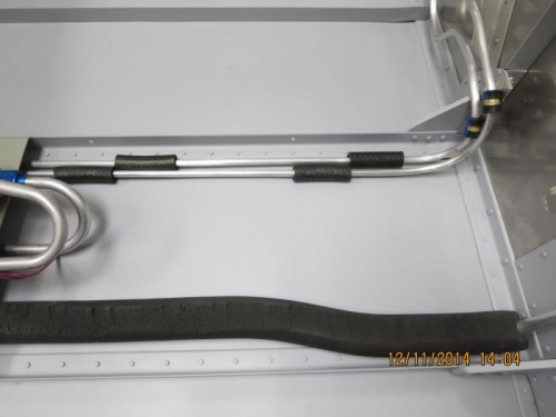
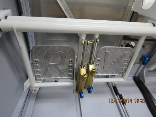
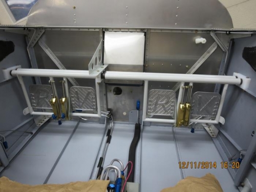
Earlier in the build I had assembled the rudder pedals and master cylinders. Before I install the assembly to the fuselage I have to install the 6 F69-F-04 x 02 brass elbows to the master cylinders as shown in DWG 36A. I also installed 2 AN822-4D elbows to the left rudder pedal master cylinders at the bottom of the cylinders as shown in DWG 36A. Next I secured the 2 brake lines that run from the brakeline firewall mount to the landing gear weldments. I used 2 adel clamps and also split some rubber fuel line to to protect it from rubbing in the center tunnel. Earlier in the build I had drilled holes in the F-719 forward skin stiffener that would support the rudder assembly. I drilled several holes so that I could move the pedals fwd or aft as needed once the seats were fitted. The bearing blocks and installation hardware were all in a bag ready for installation. I slipped the bearing blocks onto the ends of the rudder pedal tubes and placed the lowercenter bearing block in position. I placed the assembly on the forward skin stiffener and installed the AN3 bolts and secured all the hardware as called for in DWG 37.