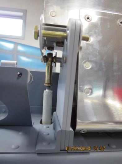
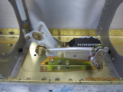
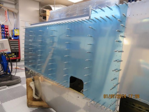
Today I started with the assembly of the 2 aileron to bellcrank push rods. The pushrods themselves were finished months ago and now it was time to install the 4 F3414M rod end bearings. DWG 15A calls for a length of 27 5/8" from eye to eye. I set this length and snugged to jam nuts. I temporarily installed the right aileron and set it to the neutral position with the jig I had made earliar. The aileron hinge bracket requires a short 3/8" spacer made from AT6-058 x 5/16" aluminum tubing. I cut the two lengths and cleaned them up on my disc sander and scotch brite wheel. I assembled the required hardware and installed the pushrod to the aileron hinge bracket. With the bellcrank in the neutral postion I had to shorten the pushrod about 3/16". I loosened the jam nut and and adjusted the rod end bearing until I had perfect alignment. I installed the hardware temporarily. Next I decided to fit the left wing lower skin. First, I adjusted all the wing rib flanges so they were flush against a long straight edge laid across the ribs. I checked several locations and made the adjustments needed with my flange pliers and fluting pliers. I clecoed the lower outboard wing skin W-705-L into place. Next I match drilled the exposed holes, moved the clecoes to the drilled holes and finished match drilling the remaining holes to #40 drill size. Next time I will dimple the skin and the ribs.