Brief Description: Construction of Emergency Battery Case
Working in the shop at home marked out the leading edge shape on a segment of 1/4 inch plywood and repeated a mirror image for two copies. Used the jig saw to cut out the shapes. Sanded the edges smooth and set aside for inserting into each wing stub. They will be placed next to the fuselage rib to maintain the leading edge shape. The foot step on the nose of the airplane causes the wing stub leading edge to become deformed.
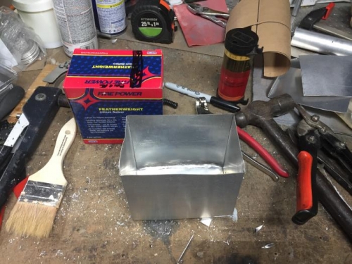
Using the battery box as a template marked out the bottom, sides and back on brown paper. Cut the paper as marked and checked it against the battery box. Transferred the shape to a segment of scrap 0.024 aluminum and cut the shape out. Marked the fold lines and bent the material to shape. Fitted the bottom and clamped it in place. Drilled a 1/8 inch hole in the front edge of the bottom lip and secured it in place with a cleo. Drilled a second 1/8 inch hole and installed a 1/8 inch pop rivet on the inside of the box. Removed the cleo and install a second pop rivet in the bottom flange. Repeated the process for the other flange to secure the bottom of the box. Bent a 1/2 inch flange on the end of a 4 inch wide strip of aluminum. Measured the width of the box and marked the strip fold line and the cutoff line. Cut the segment free from the strip and completed the edge fold on the break. Trimmed the bottom flanges at a 45 deg angle to fit on the box. Clamped the front in place and drilled two 1/8 inch holes in both sides. Installed a 1/8 inch pop rivet in each hole. Additional lighting holes will be added once the mounting position on the aircraft frame is determined.