Brief Description: Start of Instrument Panel Hole Punches
Sanded the instrument panel smooth with 220 grit sand paper. Wiped the dust from the veneer.
Used a segment of heavy copper wire to create a pattern for the trailing edge of the wing stub. Marked a segment of 1/2 inch aluminum tubing per the pattern for use as the trailing edge of the wing stub. Bent the tube in a tight bend to match the bend of the pattern. Set it aside to check the fit on the fuselage the next time at the airport.
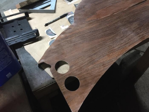
Turned the panel over and laid out the center line for the panel holes. Measured down from the mounting brace about an 1/8 inch and then marked from the template the center of the top hole. Double check the measurements. Center punched the top position. Used a step drill to drill a 3/4 inch hole at the center point. Used a 2 inch hole punch to remove the material from the panel. Checked the fit of the instrument and found that the hole was slightly too small. Used a 1 inch drum sanding wheel on a drill to enlarge the hole. Fitted the instrument in the hole and checked the spacing for the next hole. Center punched the next hole position and completed it as described above. More holes to punch in the next work day.