
|

|
|
|
Kurt Haller RV-9A
|
Date: 10-2-2016
|
Number of Hours: 4.00
|
Manual Reference:
|
Brief Description: Electrical documentation, EBUS voltage tap
|
|
Spent several evenings cleaning up the main electrical schematic and several other diagrams and lists. See example images below. Used the EAA-provided Student Edition of SOLIDWORKS for the dwgs.
I decided to connect the 2nd voltmeter input to the EMS to the non-battery side of the EBUS switch. Under normal operations, it will read ~0.5 V less than the MAIN bus, due to the Schottky diode voltage drop, If the EBUS switch is on, it reads the voltage at the + terminal of the battery, minus any losses in the 10 AWG wire. Important to have this: when and if the alternator goes Tango Uniform, the battery voltage is all there is to gauge how much juice is left (ALT out is an automatic precautionary landing!). Note that main bus volts come from the downstream side of the ammeter shunt. With the panel powered up, drawing 3-5 A, and the EBUS switch on, MAIN and EBUS voltages read the same, +/- 50 mV.
The 4 hrs is figuring out how to tie in pin2 on the EMS DB37 connector. I made a female Faston/male Faston connector by soldering a male PCB Faston tab to the back of the female. Both the EBUS feed and voltage probe line are on the nonbattery tab on the switch. See image 1. Pretty good job precision solding the male tab to female Faston, if I say so myself, But I ain't pulling it out again for a picture. This was not a easy operation even with the top fwd fuselage skin still unriveted.
|
|
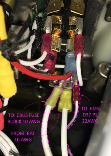
EBUS Voltage Tap
|
|
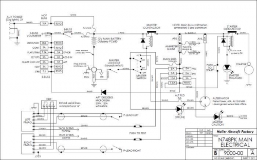
N748PK main electrical schematic
|
|
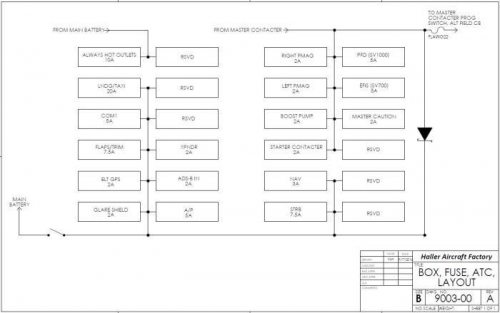
ATC fuse panels
|
|
|
|
|
|
|
|
|
Copyright © 2001-2025 Matronics. All Rights Reserved.
|