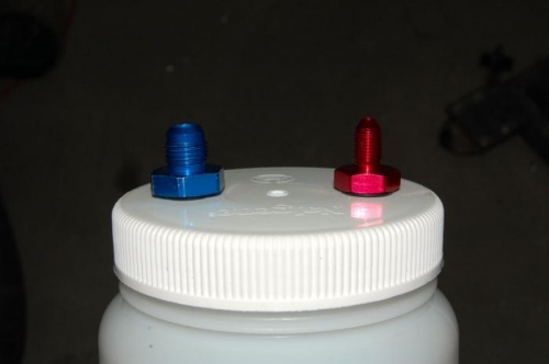
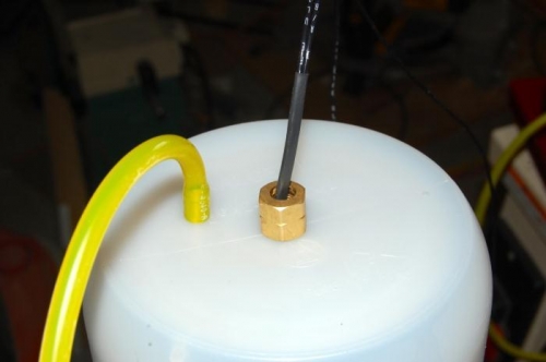
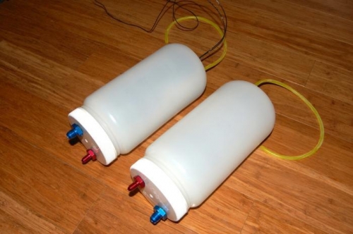
I finished the new header tanks today and I am very pleased with the results. You will notice that only one of the header tanks has a float switch, which will control when the fuel transfer pump is active. The red and blue fittings are the bottom of the tank. The red fitting allows fuel to flow from the tank with the float switch into the other tank due to gravity. The blue fitting on the tank with the float switch is where fuel from the wing tanks enter the header tank. The blue fitting on the other tank is where fuel is extracted by the jet engine fuel pump. The yellow tygon tubing is for the vent hole. There are buna rubber o-rings on all the fittings. The vent hole bulkhead is nothing more than an 0615 avex rivet with the mandrel removed. The trick is to take the rivet and remove about 3/32 by pushing the end into the deburring wheel, then using the rivet gun to pull the mandrel through without compressing the rivet. There is a small o-ring on the rivet bulkhead. The tygon tubing is very tight, and so is the rivet that was pushed through the tank after using a #14 drill bit to make the hole. The tip of the rivet was chamfered to make it easier for the tubing to slide onto the rivet. The tank was water tested and no leaks. The (3"-5") hose clamps to keep the tanks attached to the bracket fabricated in the previous post was purchased at Home Depot earlier today. Next step is to get all the fuel lines routed and the solenoids/fuel pump for the engine mounted in a good location.