
|

|
|
|
Johns Web Site
|
Date: 6-17-2015
|
Number of Hours: 3.00
|
Manual Reference:
|
Brief Description: Match Drilling the Vertical Stabilizer to the Fuse
|
|
Today the vertical spar was aligned with the fuselage. A self-leveling laser was used from the rear to align the rear spar then shimmed and clamped in position. The spar mounting holes were matched drilled to the four mounting points, then updrilled and reamed to 0.1877” for a close fit to the close tolerance NAS bolts.
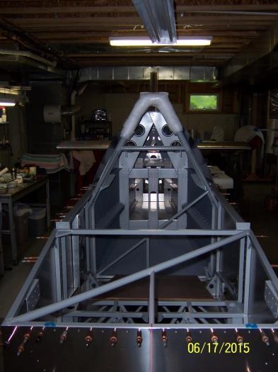
The laser was moved to the front of the fuselage and aligned with the center of the upper firewall tube, the center of the instrument panel tube, the center of the center rivet in bulkhead #1, and a mark on the center of bulkhead #3. Since the laser was set about 14-inches above and 30-inches forward of the upper firewall tube, the vertical laser line was readily visible at each of the points noted above, and also at the vertical reference lines on the front horizontal stabilizer spar, and the vertical stabilizer front spar. This made alignment of the vertical stabilizer front spar very easy. The front spar was clamped in position, and the mounting holes match drilled from the rear of the front spar as shown in Image #3. The drill was a Central Pneumatic 3/8” Angle Drill from Harbor Freight and with the #30 drill bit shortened ½” from the back end, it fit and aligned easily in the gap between the horizontal and vertical stabilizer.
Temporary fasteners and additional clamps were used to lock the two stabilizers together, and the assembly was removed from the fuselage and placed on a level bench for updrilling.
|
|
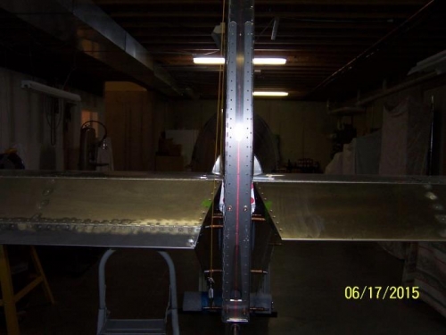
Aligning the Rear Vertical Spar
|
|
Look Closely to see the Vertical Laser Line
|
|
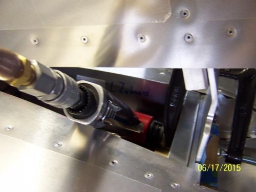
Match Drilling the Spars
|
|
|
|
|
|
|
|
|
Copyright © 2001-2024 Matronics. All Rights Reserved.
|