Completed step 4 page 21iS/U-03 for both the left and right sides after floors were painted Step 4: Riveted F-01241 to F-01224-R-1 and F-01221-R-1 and F-01222-R-1 as shown on Page 21iS/U-02, Figure 2.
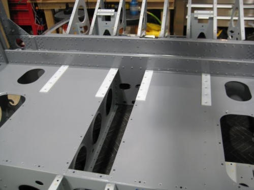
Completed steps 1-7 page 21iS/U-13 Step 1: Separated F-1203B by removing the hatched area shown in Figure 1. Step 2: Separated F-1203D by removing the hatched areas shown in Figure 2. Step 3: Machine countersunk #30 and #40 the forward face of F-01203A-1 as depicted in Figure 3 per the call-out. Machine countersunk the #30 holes 120°. Step 4: Used a step drill to enlarge the #30 holes to the sizes indicated in the detail. Step 5: Riveted F-1203B-L to the left, aft side of the F-01203A-1 using the rivets called out in Figure 4. Repeated this step for the right side of the bulkhead using the F-1203B-R. Step 6: Filed the curved recess of both F-1203C (the bevel locates the top of the part) to closely fit the rounded mating ends of the Stub Spar Assemblies of both wings then marked the parts to ensure they can be assembled on the side to which they were fitted. Step 7: Clecoed F-1203C and F-1203D-L to F-01203A-1 as shown in Figure 4. Riveted the parts together using only the two rivets called out. Final-Drilled #30 if a hole was too tight to accept a rivet. Repeaedt this step for the right side of F-01203A-1 using the remaining F-1203C and F-1203D-R.
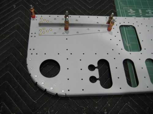
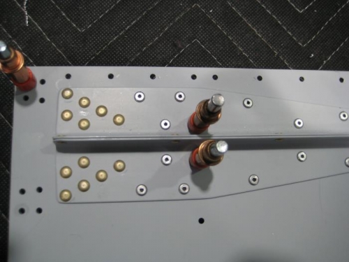
Completed steps 1-3 page 21iS/U-14 Step 1: Separated the two F-1203E by removing the hatched areas shown in Figure 1. Step 2: Riveted F-1203E-L & -R to both ends of F-01203A-1, to F-1203C, and F-1203D-L & -R using the rivets called out in Figure 2. As indicated in the figure, did not install rivets in the four holes in both sets of F-1203E-L & -R, or in the eight holes in F-1203D-L outbd of F-1203E-L & -R. Where possible installed rivets in F-01203A-1 with the manufactured heads on the forward side. Step 3: Riveted the flanges of the F-1203E-L & -R to each other using the rivets called out in Figure 2.