I had previously fabricated a Cable Wireway to hold the cables as they pass above the Rudder Pedal Assembly.
Vans, however, had agreed to ship me two replacement wireway parts (FOC) because I had agreed to do some Beta Work on the Mode S transponder fittings!
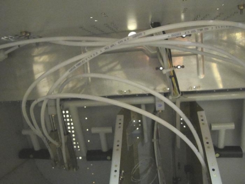
So I screwed the, previously painted, Wireway into a nutplate, securing the cable loom to the bottom of the Firewall Shelf immediately above the location of the Rudder Pedal Assembly. This is actually Section 31-13 Steps 5-7
I could now install the rudder pedals. I torqued up the bolts, then set about hanging the unit. This just requires 6 bolts to be screwed into nutplates. Sounds simple, took ages. Bet it is even harder if you try to do this with the fuselage upright instead of on its side. In fact I need to remove the central two bolts to add a Cable Bracket which I forgot. Haven't the patience to do this today.
Picture 1 shows the rudder pedals in place.
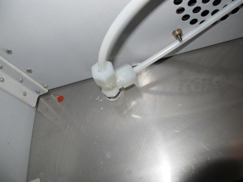
Picture 2 shows the termination on the brake pedal tubes where they pass through the firewall into the Brake Reservoir. This is actually Section 32-02 Steps 1-3.