
|

|
|
|
GA Aerospace’s Web Site
|
Date: 5-7-2018
|
Number of Hours: 10.00
|
Manual Reference:
|
Brief Description: Page 40-03 and back 16-02
|
|
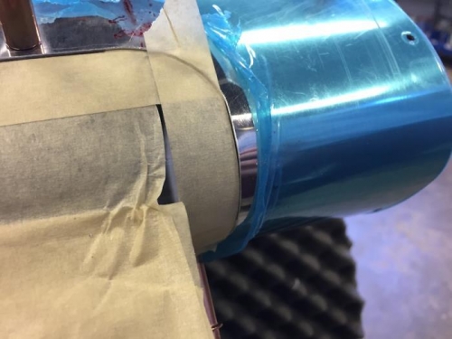
For step 3 of page 40-03 we used masking tape to mark the edges since we do not have the marker mentioned in the step. We completed step 3, 4 and 5 (40-03) in which we used a rotary cutter for this last step, step 6 could not be completed because we do not have a #27 dimple die.
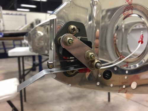
We skipped to page 40-04 and completed all of the steps (The molex pins mentioned in step 8 are included in the landing light box). On step 1 of page 40-05 we noticed that we had to have installed the two Floating 8 Pos Connectors that should be installed on section 16, so we had to go back to that section, on page 16-02.
We already got a response from Van’s saying that the torque on the nuts of this assembly doesn’t matter much, it should only keep the parts in place.
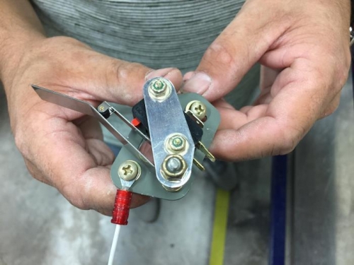
We easily completed step 5 (16-02) but for step 6, one of the nutplates had to be removed because it was a bit bent so the screw could not fit, after doing so, step 6 (16-02) was completed. We got stuck on step 7 (16-02) because when we tried to screw our stall warning subassembly on the rib, in an exact position in order for the switch to get pressed, the subassembly was rotating a bit preventing the switch from activating, we’ll try again tomorrow.
|
|
|
|
|
|
|
|
|
|
|
|
|
|
|
Copyright © 2001-2024 Matronics. All Rights Reserved.
|