
|

|
|
|
Andrews Web Site
|
Date: 7-6-2022
|
Number of Hours: 16.00
|
Manual Reference:
|
Brief Description: Fitting and adjusting flap torque tube
|
|
As mentioned in the last post, fitting the flap drive hinges in a perfect line was essential. This proved to be a challenge. I was resolved that the final tube installation must be friction free enough to rotate under the weight of the eccentric fittings only with no external pushing. This took quite a bit of shimming and adjusting. Because the inboard hinge fittings have two attach legs, they can put binding on the torque tube from very minor leg length differences (on the order of .005 inches). To further complicate the issue, all the fittings must be fully torqued before you really know how straight everything is. In the end, each attach point was shimmed using metal duct tape to get the final heights over MANY trial installation and removals. In the end, however, the tube rotates freely under it's own weight.
Image 2 shows another concern. I mentioned that the flap drive fittings are trapped between the top and bottom skins. On my right wing, I have a minor interference between the rotating fitting and where I think the top skin will be. The design appears to call for the heim fitting to be just tangent to the skin, but in my case, there is about .04 - .06 potential interference. When I fit the skin, I will need to evaluate whether the skin just moves out of the way during flap actuation, or whether I need to build a doghouse around it...or perhaps rebuild (weld) the end fitting.
Image 3 shows the rear rib members reinstalled after holes were drilled in the appropriate spots.
|
|
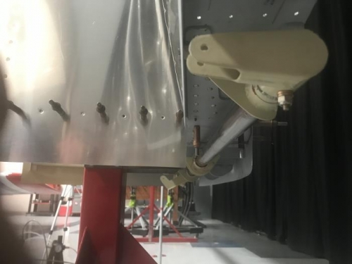
Torque tube and all fittings installed
|
|
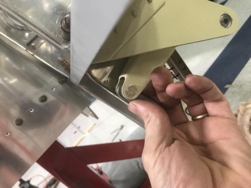
Showing close clearance to where skin will be
|
|
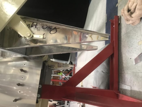
Holes cut in ribe trailing edge parts
|
|
|
|
|
|
|
|
|
Copyright © 2001-2024 Matronics. All Rights Reserved.
|