
|

|
|
|
Falcon XP Build Site (Claude)
|
Date: 2-4-2011
|
Number of Hours: 3.00
|
Manual Reference: B-5.5
|
Brief Description: Forward Pedal Assembly, Part 1
|
|
Moving on to the next section, I am working on the forward rudder pedal assembly.
The first picture shows the almost completed assembly. It's almost ready to mount in the fuselage, but I still need to secure the rudder cable to the top of the pedals. I ran out of 1/16" cable thimbles, so need to wait until those arrive before I can continue.
Speaking of thimbles and cables, the second picture shows a completed end of a swagged cable, in this case a rudder steering cable. One thing to note here is that the instructions said to just swage the cable around the steering pedal part, but I was concerned about wear if doing that. I did some checking in books by Tony Bingelis ("Sportplane Contruction Techniques") and the FAA Advisory Circular AC 43.13-B ("Acceptable Methods, Techniques, and Practices - Aircraft Inspection and Repair"). In Mr. Bingelis' book, on page 141 he states, "Notice that the terminal loop is formed around a Thimble (NA100) tto form a better bearing surface for the connecting pin or bolt. The Thimble also serves to protect the cable, and allows the development of the full 100% rated load in the cable. Should the splice be formed without a protective thimble, reliability would be compromised and cable failure may occur well below the cable's rated strength."
So, I added thimbles to these cables.
|
|
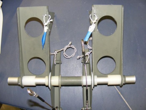
Forward Pedal Assembly Almost Ready to Mount
|
|
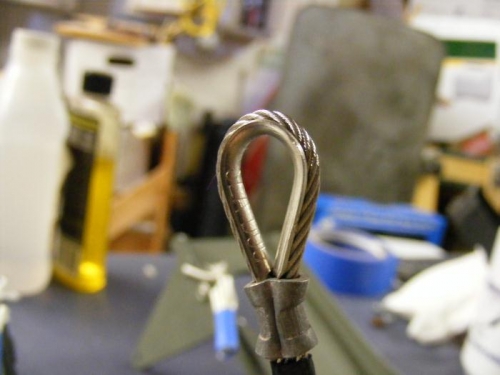
Steering Cable Swaged End With Thimble Added
|
|
|
|
|
|
|
|
|
Copyright © 2001-2024 Matronics. All Rights Reserved.
|