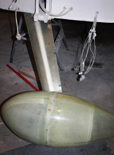
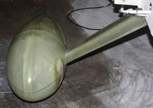
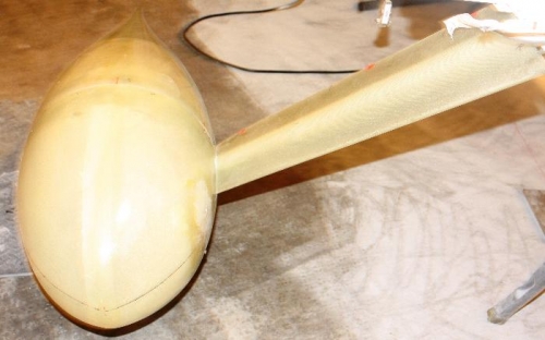
Step 1 …. I located the two U-1017A Gear Leg Fairing and according to the directions laid them on the kitchen table and confirmed there was no twisting out of the molds. Then as specified placed some tape at three places on the trailing edges and cut the tape. This is to insure that no warping is occurring while in the process of construction of the Gear Leg Fairing. Step 2 … Located the paper template on page 48-13 and cut out the template along the lines specified. Place the template over the U-1017A Gear Leg Faring Left and marked accordingly. Reversed the template and marked the Right Gear Leg Fairing. Then I trimmed off the excess using the Multi-Tool as explained in figure 1. Step 3 … I placed the marked and trimmed U-1017A Gear Leg Faring L/R on the aircraft gear leg. Checking, all seemed to be correct. The Gear Leg Fairings are very thin and light weight and appear translucent and I am betting durable. Step 4 … Removed the Gear Leg Faring from the aircraft and located the U-1017B Gear Leg Fairing Hinge. After some looking I decided to use the 063X6 ft. not the 063X3 ft. and cut this into two 26 inch pieces with about 2 feet left over. Then I marked every 1-17/32 inch along the hinge length and then go back and mark again each of these with a 1 / 4 inch mark. These will be the drill holes for riveting the hinges to the fairings.