
|

|
|
|
Conrads X-10 Build Log
|
Date: 1-17-2010
|
Number of Hours: 1.00
|
Manual Reference: 38-10, Ste 1 to 10
|
Brief Description: SECTION 38 RUDDER PETALS & BRAKE SYSTEM, Page 38-1
|
|
SECTION 38 RUDDER PETALS & BRAKE SYSTEM, Page 38-10, Step 1 to 10.
Step 1, Skipped this until I can mount the brake assembly.
Step 2, Created the F-1048G Rudder Cable Guide as described in figure 2 and 3.
Step 3, Final drilled #27 both the F-1048G Rudder Cable Guide attachment holes in the F-1048-L/R Fwd Fuselage Ribs.
Step 4, Attached both the F-1048G Rudder Cable Guide to the F-1048-L/R Fwd Fuselage Ribs. Then match drilled #27 the bottom holes.
Step 5, Removed the F-1048G Rudder Cable Guides and deburred.
Step 6, Again attached the F-1048G Rudder Cable Guide attached with AN515-6R8 screws and AN365-632 nuts.
Step 7 Repeated for the left F-1048G Rudder Cable Guide.
Step 8, Added the A-del clamp to the forward most plastic sleeve on the Rudder Cable to the F-1048-R/L Fwd Fuse Rib using AN509-8R8 screws and AN365-832 nuts, repeat for the other cable side. See figure 6 for further detail.
Step 9, Skipped this until I can mount the brake assembly.
Time about 1 hour.
|
|
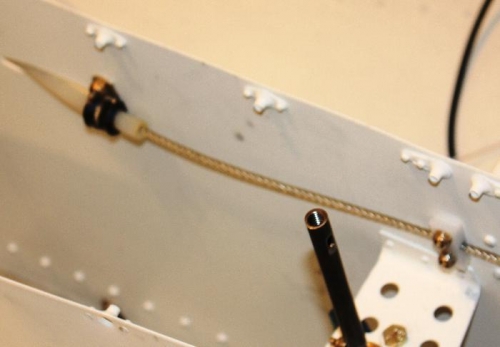
A-Del Clamp and F-1048G Rudder Cable Guides
|
|
|
|
|
|
|
|
|
Copyright © 2001-2024 Matronics. All Rights Reserved.
|