
|

|
|
|
Conrads X-10 Build Log
|
Date: 10-26-2009
|
Number of Hours: 4.00
|
Manual Reference: 31-7, Step 1 to 5
|
Brief Description: Section 31 UPPER FORWARD FUSELAGE ASSEMBLY .. Pa
|
|
Section 31 UPPER FORWARD FUSELAGE ASSEMBLY .. Page 31-7, Step 1 to 5.
##################################################################
I passed the 1000 hour mark in this project today. Therefore I believe that I am at least 1/3rd of the way through the X-10 project !! :)
#################################################################
Step 1, I then Attached the F-103B, Inst Panel Lower Flange and F-1003C-L & R Instrument Panel Attachment Flanges to the F-1003A Main Instrument Panel as shown in figure 1. Then I used the crimping or fluting pliers to create a near perfect fit of the F-1003D-E Instrument Panel Attach Flanges to the edge of the F-1003A Instrument Panel.
Step 2, I attached the F-1003A, F1003B and the F1003C-L/R Inst Panel Attachment Flanges with AN526C832R8 Stainless Steel screws then to the F1044A, F-1045R –L Fwd Fuse Channels as shown figure 2.
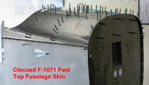
Step 3, Cleoed the F-1071 Fwd Fuse Top Skin after removing the blue protective wrap and deburring the sharp edges to the top flanges of the F-1001A,F1003C-L/R, F-1044A F-1045-L/R F-1068A, F-1068-L/R and the the F-1040-L/R Fwd Fuse Ribs.
Step 4, I deburred the sharp edge and bent the F-1071 Hand Hold Doublers to fit the curvature of the top skins. Then clecoed the F-1071 Hand Hold Doublers to the place they were designed. The March-Drilled #40 the holes and Final drilled #40 the exiting holes in the F-1071 Hand Hold Doublers. Finally I traced around the F-1071 Hand Hold Doublers for where not to dimple.
Step 5, Now I final drilled #40 all the holes that I found in the F-1071 Fwd Fuse Top Skin and rotated clecos as I went.
Time about 4 hours.
|
|
Ready to Final Drill with #40
|
|
|
|
|
|
|
|
|
Copyright © 2001-2024 Matronics. All Rights Reserved.
|