Step 1, I located the Instrument Panel F-1003A and proceeded to drill a ¾” hole for the A-510-2K Magneto Ignition Key Switch. I drilled the hole according to figure 1 and used the template on page OP37-19 to complete the fit.
Step 2, I enlarged the tooling hole I the F-1068B-L Sub Panel Side for a 5/8” diameter hole that will contain a SB625-8 bushing.
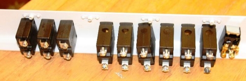
Step 3, Studied the SCB/CB configuration as in figure 3.
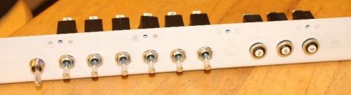
Step 4, I screwed the WH-801 Rt Console Template to the F-1003B Instrument Panel Lower Flange at the two alignment holes. Then after following figure 4, I drilled with #30 drill bit a set of 13 pilot holes. Realizing that I will need at least one additional 20 amp SCB for the second set of landing lights and one 15 amp SCB for the heated pitot tube assembly. Then using a unibit I drilled the 1/8” pilot hole to 15/32” diameter, clamping the instrument cluster to prevent movement.
Step 5, Installed the series of SCB’s and CB’s in preparation for the next chapter.