Brief Description: Section 29, FUSELAGE SIDE SKINS …. Pages 29-4, St
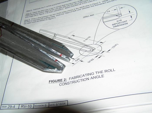
Section 29, FUSELAGE SIDE SKINS …. Pages 29-4, Steps 1 to 4 Step 1, I created the Clamping Block from a piece of tightly grained Douglas Fir, after looking at Home Depot and Lowes for a piece of 2 X $ hardwood that did not exist. I know it’s not really hard-wood as the design calls for but it worked. And the results were true to the dimensions called out but I used a Saws-All and wood chisels so it turned out a little rough. Remember you only use this tool once for each of the 4 side panels and then toss it. Step 2, I fabricated the F-1070A and B Roll Construction Angles out of aluminum angle tubing as shown in figure 2. Step 3, After constructing the F-1070A and B Roll Construction Angles I clecoed the #40 hole in the nose to the F-1070-R Mid Side Skin. Then marked the F-1070-R Mid Side Skin L/R as indicated in figure 3. Then Match Drilled all the holes along the bottom of the edge of the side skin of the Mid Side Skin into the F-1070A and B Roll Construction Angles. Step 4, O I then drew the Roll or Bend Line as shown in Figure 3 to start the Bend procedure on the following page. Time about 3 hours because I needed extra time to create the Clamping Block.