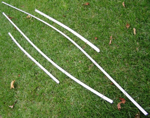
Section 29, FUSELAGE SIDE SKINS …. Pages 29-3 Steps 1 to 4 Step 1, Basically using the same techniques as previously I formed the curves using the flip side of the F-1046B Longeron Bending Template. I taped and then placed into a vice the Aluminum Angle and with a rubber mallet formed the Left and Right F-1013 L/R Mid Fuse Longerons using the Template to with 1/16” of an inch. Step 2, Placing both the Left and Right F-1013 L/R Mid Fuse Longerons in the vice I set the F-1046B Longeron Bending Template set to the F-1013 right side on top then I taped firmly in place with the use of C-clamps to ensure that the template won’t move when I drill a series of #40 holes following the hole pattern in the top of the template into the F-1013 L/R Mid Fuse Longeron. Step 3, This step only apples to the Right F-1013 Mid Fuse Longeron as the instructions do not mention performing the bending maneuvers to the Left F-1013 Mid Fuse Longeron. After clamping in a padded vice at the previously marked fwd twist mark I used a vice grip set of pliers and obtained the 2 degree bend or twist in the aft and forward ends of the Right F-1013 Mid Fuse Longeron. Checked a few time to be sure but the curve I created seemed OK. Step 4, Deburred all the #40 holes in both the Left and Right F-1013 L/R Mid Fuse Longerons. Time about 2 hours because I worked slower than usual.
Completed F-1013 and F-1046 L/R Mid Fuse Longerons