Started with the install of the GSA 28 servos since they are part of the CAN BUS and I need to know the wire run and length from the avionics bay, so I can determine with wire (Roll or Pitch) I am going to splice to create the CAN BUS Hi-Lo connector for the GMA 240.
No reason I can't do this while Jeremy can find some free time for me - lol
There is just no way I can read the entire 700+ pages of the G3X Installation manual, plus the manual for the GTR 200, and now the GMA 240 and understand everything I need to know at the outset. Usually it comes in stages as I work through the installation, as is the case with the GSA 28 servos.
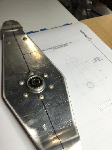
I realized the bell crank brackets already riveted to the airframe need to be replaced by the Garmin supplied brackets which secure the servo. I'll do that later, for now I remove the bell crank, located the center line, and marked 2" up, and .40 inches back to locate the #11 hole for the rod end bearing of the connecting rod for the servo.
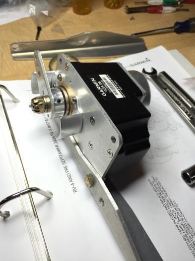
GSA 28 Servo mock up to bracket
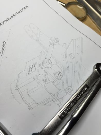
GSA 28 Servo Install diagram
Elevator Berll Crank / GSA 28 Rod End Bearing locatino