Brief Description: Rudder Horn and Counterbalance Assembly
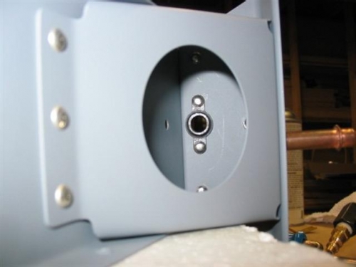
Here the counter-balance rib is riveted into place at the top of the spar. See the two forward-most big countersunk holes? This is where the two bolts will hold the lead counter-balance in place. It's funny, you try to build an airplane as light as possible, then you go and add lead weight to it. You definitely want the lead counterweight to balance the controls, but it's just a funny irony of the way things have to be.
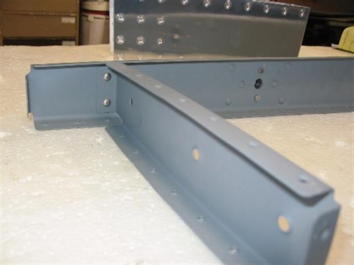
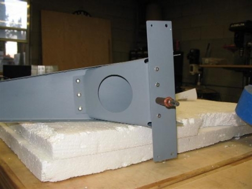
The horn brace is installed in the pictures below with exception to one LP4-3 pop rivet (or should I say, blind rivet?). I think I might have been shorted in the kit because I ran out of the LP4-3 at this point. A friend of mine who has built an RV-7 empennage gave me a few of his extras. I did inventory my kit prior to building, so I'm not sure of what happened here. Maybe the count on the drawing vs. the count on the inventory list is off......who knows! Note that I build as much as possible on the Styrofoam blocks shown. This tends to keep scratches and dings to a minimum.