
|

|
|
|
BRUCE'S WEB SITE
|
Date: 4-7-2013
|
Number of Hours: 7.50
|
Manual Reference:
|
Brief Description: Wiring, wiring, wiring...
|
|
Finished wiring of J10 connector by installing the power wire for the left P-Mag. Shrunk down the heat shrink and clicked the white part of the connector into the shell. Installed onto the VP-400. Began wiring the J12 connector. Installed in order: EFIS PFD power on P1, Strobe Light power on P2, SL30 power on P3 (different than originally planned, thought it would be two separate power wires for Nav and Com but Stein wired them both together), Ground wire to P4, and then Flap motor wire to two pins, made a Y wire to connect the single flap motor wire to two different pins, P5 and P6. Then wired the right HID Landing light to P7, the Accessory Power Plug to to P8, the VP-400 Display power to P9, the right P-Mag to P10, the Alternator Field wire to P11, and finally the Nav ligths to P12. All wires had to have the pins crimped on prior to install and I labeled everything as well. I then began wiring the J8 connector. I installed the transponder wire to P1 first. I then crimped all the male DB9 pins onto appropriate length wire and installed into a DB9 connector for the ADS-B power and data. I then installed the ADS-B power wire into P3 of the J8 connector. I then began the wiring of the J1 connector. As before, I crimped all the pins onto the wires for everything as I was installing them. I installed the CO Monitor wire into P1,and the Hobbs power into P2. I had to re-route the trim wires slightly from the right hand side of the firewall indent to the left side to align better for the wiring. I installed the +2.5V Wht/Blu wire into P8, the Ground Wht/Or wire into P9, the Pos Input Wht/Grn wire into P10, and the two trim motor wires into P11 and P12. I drilled another large hole in the subpanel bulkhead to put a grommet to run a lot of the wires through for good routing. I installed the right Fuel Sensor power wire into P14 and the left Fuel Sensor power wire into P15. I re-routed the flap position wires a little like I did the trim wires and I installed the Flap Position input wire into P17, the Flap
|
|
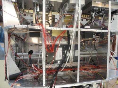
Top down view of wiring so far
|
|
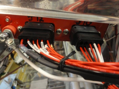
The J10 and J12 done.
|
|
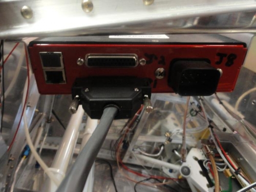
The J1 done and installed
|
|
|
|
|
|
|
|
|
Copyright © 2001-2024 Matronics. All Rights Reserved.
|