
|

|
|
|
BOB'S WEB SITE
|
Date: 7-6-2020
|
Number of Hours: 3.00
|
Manual Reference: Section 46
|
Brief Description: Wired up crankshaft position wires
|
|
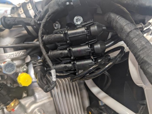
Following up on yesterday's post, Tony Kirk at Van's confirmed that I should have removed the left side of the wires and routed them as the instructions indicated. And the connector that holds them in place doesn't pull back, it pulls out. Duh. After considerable looking at the instructions, I ran the wires and then tie-wrapped them.
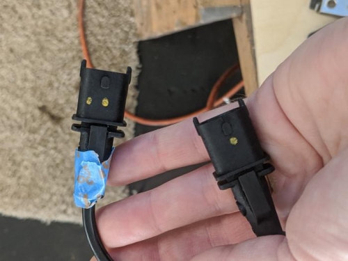
The instructions talk about a yellow mark to indicate where a particular connection goes, but my Rotax instead had two yellow dots on one wire (and the position sensor) and one yellow dot on the other. I initially surmised that it must also indicate which is CPS-1 and which is CPS-2. But the configuration that came from the factory had the two-dot wire connected to the wire with the text label CPS-1. I ended up reconnecting everything the way it came from the factory after rechecking the pictures I took before disconnecting everything and noting the marks *I* had made on connectors to be sure they were going back the way they should. Tony said as long as the upper sensor is connecting to the upper connector it should be fine. That tracks perfectly.
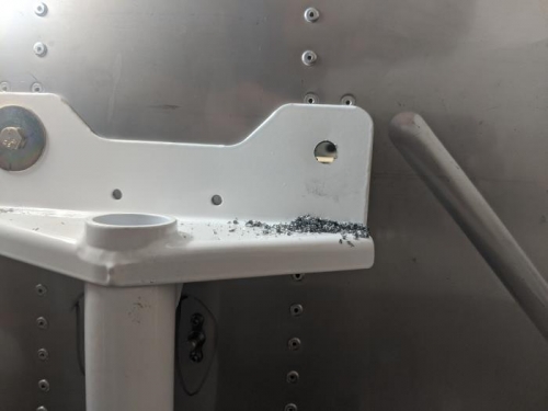
Next, I turned attention to drilling the firewall for the mount plates. I made a small bushing and installed hardware on the right side of the firewall and gear mount and then torqued everything down with a AN3-5 while drilling the left side out to 3/8", first using a 5/16" bit and then I discovered the old Avery Tools reamer for these bolts from the RV-7A I built. Slightly undersized at .3774, I believe. Anyway, it came out perfect.
I wanted to drill out the hole on the right side, too, but the nut called out in the instructions wasn't in the packing list so I have to investigate what that's all about.
|
|
|
|
|
|
|
|
|
|
|
|
|
|
|
Copyright © 2001-2024 Matronics. All Rights Reserved.
|