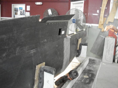
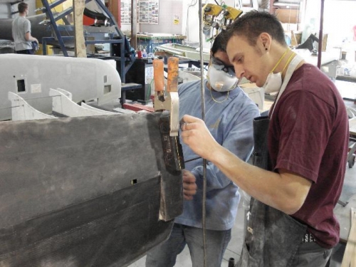
Control horn had to be installed on one elevator in order to perform this step. Then, elevator was mounted onto horizontal stab (see picture 1). From here, elevator was aligned with horizontal to neutral position (elevator paddle at the tip was aligned with upper and lower skin of the horizontal stab to achieve same amount of clearance on top as on bottom). Digital protractor was clamped to elevator (see picture 2) and then set to zero (0 deg). New, elevator was rotated around travel axis until control horn stops came in contact with horizontal stab's skins. Skins were notched in these areas until elevator was able to rotate to 26 deg in up and 11 deg in down direction.
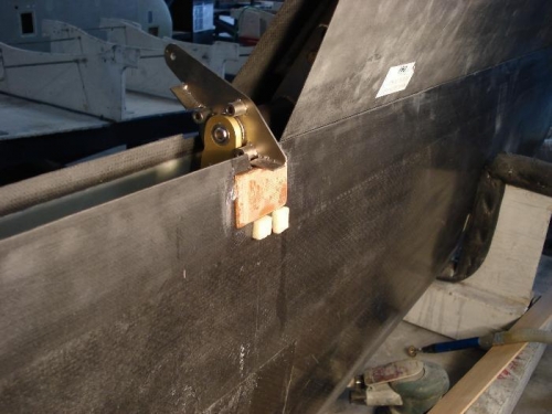
Once specified travel was set, phenolic blocks were cut and bonded in line with notches made in skins (see picture 3). Later, once adhesive was set, 4 BID layup was applied over phenolic blocks as a reinforcment.