
|

|
|
|
TERRY'S WEB SITE
|
Date: 1-25-2015
|
Number of Hours: 4.00
|
Manual Reference:
|
Brief Description: Continue AeroVee Engine Assembly
|
|
Dissassemble flywheel and shims from crankshaft.
Install shim pack, all OEM shims from kit, which measures .055".
Apply Permatex High Temperature Red RTV Silicon Gasket Maker, Item #881160 (26B) to outside of ACV-P01-68 Oil Seal, install seal in crankcase. Tap in until it is flush with the case (not all of the way in, this would cover the oil holes in crankcase. This should be noted in the assembly manual).
Clean crankshaft and gland nut threads with acetone.
Apply silicon to inside of ACV-F01-02 Flywheel Assembly, install same.
Apply Loctite 242 to inside of crank threads & ACV-P01-42 Gland Nut, install & torque nut to 227 ft/lbs.
Check magnet installation / orientation on the flywheel & bolts are tight (all OK, was already assembled when received).
I previously mounted ACV-A01-19 Ignition module x 2 to ACV-A01 Accessory Plate.
Attach Accessory Plate to engine case.
ACV-Z01-20 bolt that attaches with nylock nut is too short, is 75 mm, used 80 mm.
Torque mounting bolts to 25 ft/lbs.
Set ignition modules for .010" gap, tighten same.
Paint magnet with black marker, rotate crank & check for contact with ignition modules, OK.
Rotate crankshaft until magnet is @ top, witnes hole "T" @ top (this is NOT @ 12:00 as instructions say, but part way to 1:00. DWG also shows this NOT at 12:00. Instructions call for 9/64" hex drive, is actually 5/32".
Install ACV-F01-24 Trigger Shaft Assembly 20 Amp, Loctite 242 on screws.
|
|
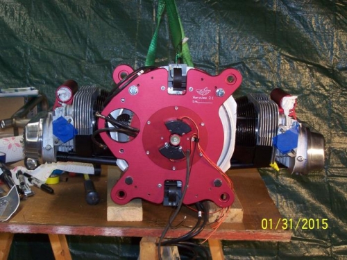
Accessory Plate Mounted to Engine Case #3844
|
|
|
|
|
|
|
|
|
Copyright © 2001-2024 Matronics. All Rights Reserved.
|