Brief Description: Brake pedal and Master cylinder assy continued
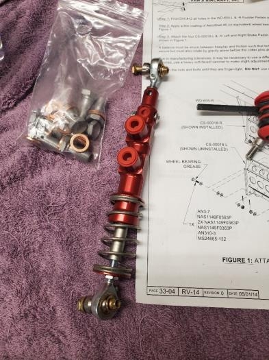
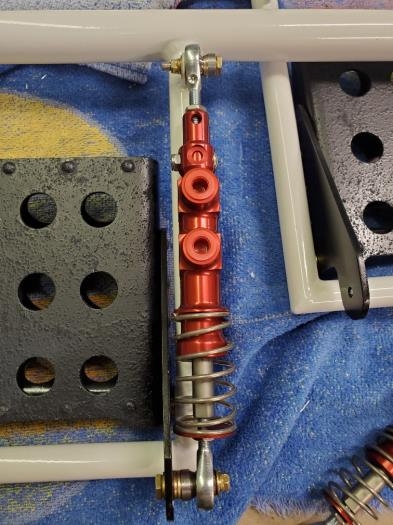
I assembled the master cylinder per the Beringer diagram. Pretty simple once i found the correct document. Then I attached them to the pedal assemblies. I used various combinations of the called for washers to get a proper vertical alignment with the post and to give clearance from the spring touching the pedal bracket near the bottom attach point. Before attaching the master cylinder you need to adjust the top and bottom rod end "turn buckles". They screw in and out to adjust the angle of the pedal itself. I adjusted all 4 the same way which was a mistake. Since the rudder pedal assemblies are 2 separate tubes that are offset fore and aft in final installation, the left pedals will have different angles than the right pedals in relation to each other in there respective assembly tubes. This sounds confusing but will be apparent when you put them together. Because the tubes are offset fore and aft, in order to get the pedals to feel even on your feet, the left pedals will have a different angle than the right pedals, when final assembled. I also used a longer AN bolt in the bottom attach point (AN3-11A vs. AN3-10A). This is because the washer stack I used didn't leave enough enough threads for the nut to be attached correctly.
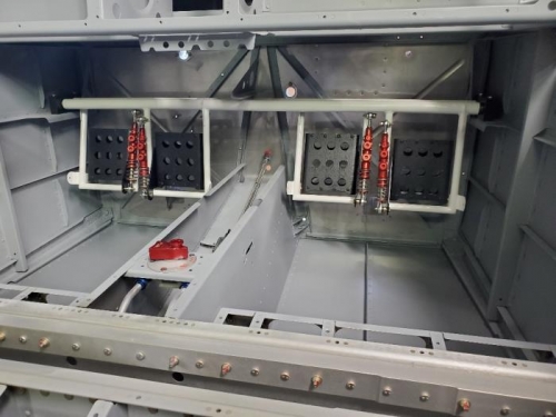
Per the Van's manual, I attached the end blocks and set them in place. I haven't completed this installation as the center block caused too much friction so I will tackle that next time.
Assembled master cylinder
Attached master cyl and washer stack
End caps installed and placed, pedals still need final adjustment