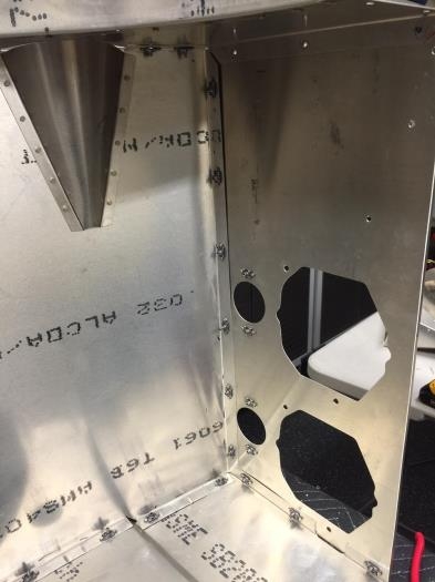
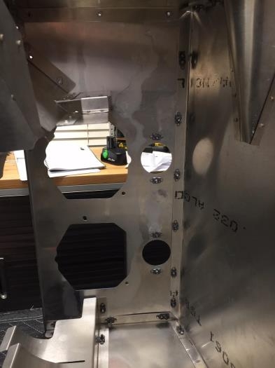
Brief Description: Back in the World of Nut Plates…Oh Joy!
67 nut plates need to be installed on the engine shroud alone. I haven’t done this for a while, so I needed to get back in the rhythm of things, beginning with setting up enough drills so I wouldn’t have to keep changing bits. Here is the process:
Step #1 – Confirm and mark the location and side of the metal where you will be installing the nut plate. Step #2 – Drill out the pilot hole to the size of the nut plate jig you are using. Step #3 – Place the jig in the guide hole and orientate the jig so it’s aligned for proper plate placement and angle. Step #4 – Use a strong spring clamp to help hold the jig from rotating. Step #5 – Using a #40 drill bit, drill through the jig using a backing block to catch the bit. Step #6 – Remove the spring clamp and reverse the jig. Step #7 – Reapply the spring clamp and drill through the second hole. Step #8 – Remove the jig and drill out the center hole to 1/4” to accommodate full movement of the floating nut. Step #9 – Deburr all of the holes you just made. Step #10 – Using a rivet squeezing tool and a countersink bit set, counter sink for flush rivets. (Make sure to countersink the correct side!) Step #11 – Cleco one side of the nut plate in place. Step #12 – Change out the countersink bit on the squeezer with rivet bits. Step #13 – Measure for the correct length of rivet and install the first rivet in place. Step #14 – Remove the cleco and install the second rivet. Step #15 – Run a tap through the nut plate if you plan on being able to remove the screw several times during the installation. Step #16 – Repeat 66 more times…..oh dear God….