Brief Description: Page 366 Started Wiring the ACI Wire Buss
September 1 2013
Started Wiring the ACI Wire Buss
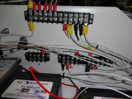
I took out the long buss bar under the grounding bus on the avionics tray and replaced it with 3 short buss bars. The ACI wiring diagram wanted 2 buss bars and I wanted an extra one for a always powered buss for the clock and auxiliary power receptacle.
I connected the (1) and (2) buss bars to the ACI Power Buss and the (3) buss bar to the main battery contactor connection. This way if the clock should run down the battery, I will still have the backup battery to start the engine.