
|

|
|
|
Sonnys CH650
|
Date: 8-29-2011
|
Number of Hours: 1.50
|
Manual Reference: Dwg 6T2-4
|
Brief Description: Cut Out Stabilizer Skin
|
|
Cut out an 875 x 2240 blank from 0.020 and marked the center line (1120mm from right and left edges). Measured distance from bottom rear spar web to front attachments and distance between the attachments. Transfered these dimensions to the skin then sat the stab skeleton on the skin to trace the attachment profiles to be cut out.
9/20/11 Tip: It is possible to layout and drill both the bottom and top rivet holes to have a skin that is pre-punched like one you would receive from ZAC. Before bending the skin mark a line end to end at 425mm from bottom edge (confirm it is also 450mm from the top edge). This line will 1) confirm the bend location and squarenss and 2) serve as a mirroring reference between the top and bottom.
Lay out the skin using simple cartesian coordinate system with the left edge being "0" in the X direction and bottom edge the "0" in the Y direction. Making all measurements from a single reference eliminates the the potential for tolerance stack that can occur when measuring from locations that were measured from other locations that were measured from . . .
Measure out and mark the rib rivet lines at 27, 280, 640, 960, 1280, 1600, 1960 and 2213 from the left edge. Confirm location and accuracy by measuring these same lines out from the center line (as shown on drawing 6T2-4).
Measure spar line distances from rear web to center of spar flanges. Layout the top and bottom spar lines on the skin: 11mm to rear spar (lower), 33 and 273 to (bottom) rib end holes, 295 to front spar (bottom), 555 to front spar (top), 577 and 817 to (top) rib end holes.
|
|
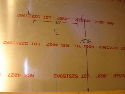
Front Attachment Hole Locations
|
|
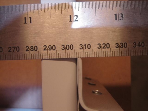
Rear Edge to Front Attachements
|
|
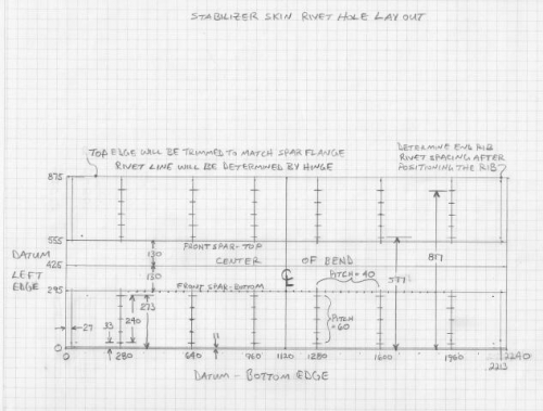
Skin Layout
|
|
|
|
|
|
|
|
|
Copyright © 2001-2024 Matronics. All Rights Reserved.
|