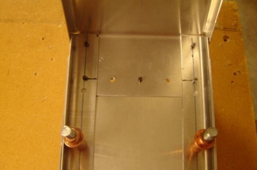
The process for locating and drilling the seven holes to attach Rib #1 is not well defined in the drawings, construction standards or other builder logs that I could find. I had already drilled the doublers down to the bottom of the spar on a 40mm pitch (exact measurements in this case) moving down from the top. I should have designated the bottom holes in the spar as a "no rivet zone" to ensure that my line of rib rivets would not interfere. In the picture you can see my original hole which fell just below the top edge of the rib flange. These holes can not be used so I confirmed with Caleb that they would be ok to leave as-is.
My method for locating and drilling the rib holes was a little unorthodox so I'm not going to document it here. The results are acceptable but would do it dfferently a second time.
Key lesson: Lay out all rivet lines and double check dimensions to verify they conform to the drawing and construction standards - especially edge distances and pitch. The only way [I could determine] to create accurate hole locations required opening up the rib flange bend to 90 degrees to permit access to the lower holes for marking and drilling. Marking and drilling from back side would require the drill length be restricted to ensure it would not contact the lower surface of the rib.