Brief Description: Finished up power & ground wiring from the radio s
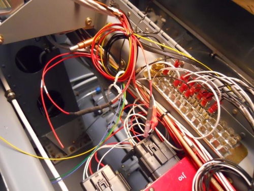
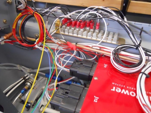
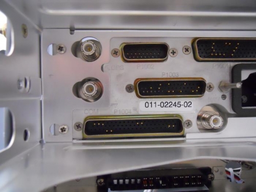
I attached radio wiring harness to the trays and installed the trays. I replaced some clamps and added others in order to “tidy up” the wiring mess. I connected my “E” bus wires to the power wires from the GTN650 using a butt splice, then covered with shrink wrap. My “E” bus wires are connected to toggle switch which will toggle between power to the GTN650 through the VP-X or directly from the battery in case of an alternator failure. I also connected the power wires for the ICOM A210 and the GMA240 to the VP-X. Next, I terminated all 6 ground wires from the radio bundle with fast-on connectors and connected them to the ground tabs. While verifying power and ground wires in order to properly label them, I believe I found an issue with one of the connectors on the GTN. It appears that the pins were inserted into one of the connectors as if looking at the connector from the wrong side. If I’m correct, I’ll just remove the 8 or so pins and re-insert into correct location. I’ll have to do some further investigation on this issue.