
|

|
|
|
Project Blue Angels SeaRey
|
Date: 12-1-2013
|
Number of Hours: 10.00
|
Manual Reference: None
|
Brief Description: Wiring all EMS sensors, part 2
|
|
All sensors are wired, but now I had to finish wiring up the connector to the EMS computer.
I've soldered a lot in my life, but my technique really wasn't up to par for this kind of work, so I really had to study, learn, and practice before I had aviation-quality connections. I eventually got a good flow of using the flux, tinning the lead wire, dropping some solder down the connector hole, placing the lead in the hole, and in a second of heat from the iron, it would drop down and be permanently soldered. These are tightly arranged 37 pin D-subs, so it’s also important be able to magnify what you’re working on.
In addition to all the engine sensors, I also connected of configured my elevator trim in the Skyview display, since it is also wired to the EMS module. This was actually a lot easier than I thought it was going to be, it was simply orange wire to pin 18 (+5v), blue wire to pin 3 (ground), and green wire to pin 9 (or any open general purpose input). There’s then a configuration where you run the trim between the up and down extremes, then define the takeoff position. (NOTE: pin 18 also powers the fuel and oil pressure sensors)
Now that the EMS hookup is done, the Skyview allows the pilot to arrange the sensor readouts anywhere on the screen and display in a variety of ways, so that will be an ongoing task of finding what works best for me.
|
|
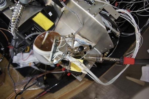
Soldering the D-sub connections
|
|
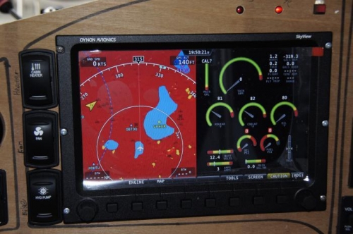
After programming the Skyview, I'm getting a reading from all sensors
|
|
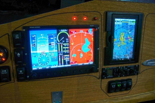
Configuring the screen to closer to how I'll fly with it
|
|
|
|
|
|
|
|
|
Copyright © 2001-2024 Matronics. All Rights Reserved.
|