
|

|
|
|
Jims Web Site
|
Date: 8-16-2010
|
Number of Hours: 6.00
|
Manual Reference: (none)
|
Brief Description: Installed TB1
|
|
1. Updated electrical drawing, sheet 2, to reflect strobe disconnects, aileron and rudder trim, and landing/taxi light.
2. Created label for TB1
3. Positioned TB1 under pilot seat, and drilled mounting holes. TB1 must be installed with two machine screws, as adjactent heads would interfere with each other.
4. Mounted TB1 with 2 6-32 screws, 2 AN960-5 washers, and four #6 nuts. Nuts are used in "jam" configuration, as a lock nut will not fit.
5. Lugged and mounted TB1 end of wires 6KF21-25.
6. Routed wires 6KF21-6KF25 through center console.
7. Lugged and installed landing and taxi light wires 6PF27 and 6PF29.
8. Routed wires 6PF27 and 6FP29 through center console.
9. Created wire bundle of 6KF21-25, and 6PF27 and 29. Secured with sna0p ties.
10. Installed two adel clamps to hold above bundle.
11. Integrated bundle into center console wiring harness.
12. It was impossible to get a photo of myself installing the termijnal stirp and wires, due to close quarters. The third phot is of my arm immediately after installation, and shows the result of the close quarters.
|
|
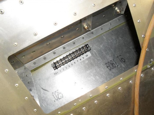
TB1 installed on floor under pilot seat
|
|
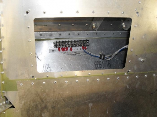
Fuselage wiring connected to TB1
|
|
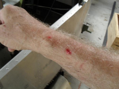
My arm after fishing wires from TB1 through center console
|
|
|
|
|
|
|
|
|
Copyright © 2001-2024 Matronics. All Rights Reserved.
|