
|

|
|
|
Jims Web Site
|
Date: 3-6-2012
|
Number of Hours: 5.20
|
Manual Reference: (none)
|
Brief Description: Wired and mounted the comm transceiver
|
|
The MGL V10 appears to be a good choice for a new comm transceiver, because of size, weight, flexibility, and cost. However, the wiring is a bit tricky. Mic lines must be shielded separately, as must headset audio.
The V10 uses a db25 connector for everything except coax to the antenna, and all the pins of the db25 are in use. This makes soldering tricky and time consuming.
1. For each wire:
A. Cut each wire to length, and stripped the end(s).
B. Verified that each wire went where the tag said it did.
C. Soldered each wire to the appropriate db25 pin.
D. Slipped heat shrink insulation over the solder joint, and applied heat.
2. Ran the power ground to the approprite pin.
3. Made a hook splice between the two ptt grounds, and routed them to one of the audio input grounds.
4. Wrapped the shields of the 3 audio cables with wire, and soldered to the shields.
5. Ran this shield ground to the second audio ground.
6. Placed heat shrink over the entire assembly.
7. Performed quick wire debug/ringdown to check for continuity and shorts.
8. Assembled connector.
9. Installed comm in panel using #6 screws.
10. Installed coaxial cable and db25.
|
|
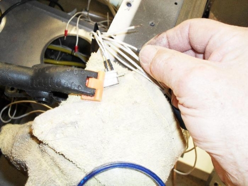
Soldering the wires to the MGL comm connector
|
|
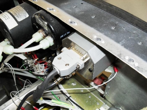
Connectors mounted to the back of the comm
|
|
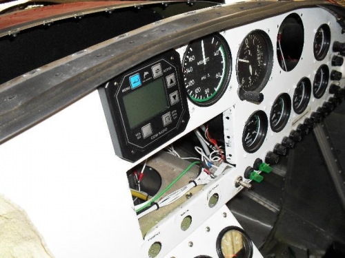
Comm front view
|
|
|
|
|
|
|
|
|
Copyright © 2001-2024 Matronics. All Rights Reserved.
|