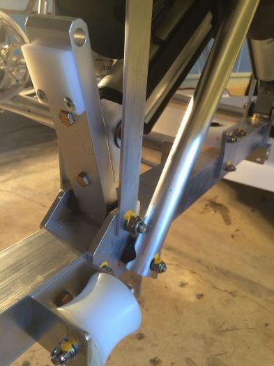
With the time coming nigh to insert the aluminum frame in the FRP hull for the final time I started checking all my previous work, cleaning the parts labels off and torquing and marking all the bolts. I used Varsol paint thinner, a thin bladed spatula, the scouring pad that came with the KeelGuard and a cloth to do the clean up and they worked well on both the aluminum and FRP parts; removing linseed oil, labels, torque seal and red marking pen without scratching either the aluminum or the FRP gel coat. In this section I had to do more than just check and clean as I found that I had installed the Retraction Bars left to right in step 3, i.e. I had the spacer pads to the inside of the frame instead of to the outside. Once I took a lot of things apart and re-installed I then realized that the two AN4-10A bolts holding the Actuator Clevis onto the Retraction Bars were upside down... so every #$%$ thing had to come apart again. I started wondering if the standard AN4-17A bolts in step 5.1 should be drilled AN4-17 but decided to think more about that later. This question is coming up in a number of other instances where the joint is a rotating one. I have not gone beyond step 5 in this section as it would appear that the frame really should be inside the hull at this point. 25 May 2015 update: the actuators are actually unpside down in these photos!!!