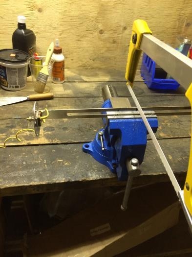
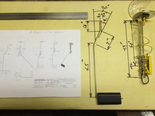
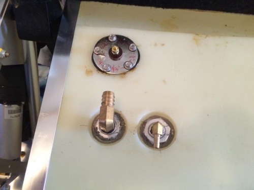
My kit came with the new 23 gallon fuel tank and a new fuel gauge sender. First I took the sender out of the tank that was marked "remove". Then following the "old" manual instructions Section 4, starting at step 2, I worked in conjunction with the new drawing that came with the new sender (2810-008). So for step 2.2 I made the cutting line for the support arm at 7.5" and made a mark at 6" for step 2.4. Then for the float arm I cut it to 10.25" in step 3.1 and made the bends per the drawing instead as per step 4.1. Following me? For step 5.1 the length is 0.25" and for step 6.1 the gasket is rubber not cork. The marked length in step 6.2 is 6" (you are following me now, aren't you?). So basically just follow the general instructions of old Section 4 but use the dimensions provided in the drawing 2810-008. I then inserted the sender into the fuel tank per step 7 but in step 8 I used 3/4" hex head screws instead of the 1/2" machine screws because they seemed to have the necessary length to grab the threads and seat themselves. Whether they came with the new sender or the old sender I don't know because now I was so confused that it was time to call it a day. But all in all I am confident that I got the installation right.