
|

|
|
|
Bob's Searey LSX Web Site
|
Date: 6-12-2015
|
Number of Hours: 6.00
|
Manual Reference: Section 16
|
Brief Description: Assembling Wing Frame - stbd - final
|
|
WOW... this is a long section... 71 steps though I didn't do the last four as I don't yet have an Angle of Attack (AOA) sensor to install, plus it goes in the port wing anyway and I am working here on the starboard wing.
Step 6, which has you riveting the Leading Edge Wing Cuff to the Support Angle and Secondary Support Angle, had me scratching my head because the instructions on where to rivet do not match where these particular angles lie under the cuff. I double checked back to steps 26 and 27 for the proper location of the angles and what I had done looked correct. I have to surmise that the instructions in step 61 are off for whatever reason, specifically the location of the required rivets given in steps 61.1 and 61.2. Basically I think you have to put the rivets where the cuff lies over the angles following the general idea of the instructions but not the specifics. OK? Simple. Unless I am completely wrong of course.
My generous friends in Nelson, BC, Glen and Bob, sent me the cuff bending tool described in step 62 which I put to good use. You can see it in the first photo below. They also sent me their wooden template for locating the slot to cut for the Wing/Strut Plate in the Leading Edge Wing Cuff. Thanks guys!
Alright, so the starboard wing frame is assembled to the point that the fabric covering is the next step, a big step, and some time off as I have to get the port wing up to this stage and then I have to get the government appointed inspector to come and sign off on my progress to date.
|
|
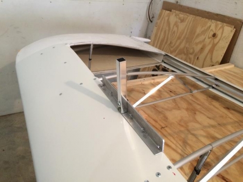
tool for bending the cuff edges
|
|
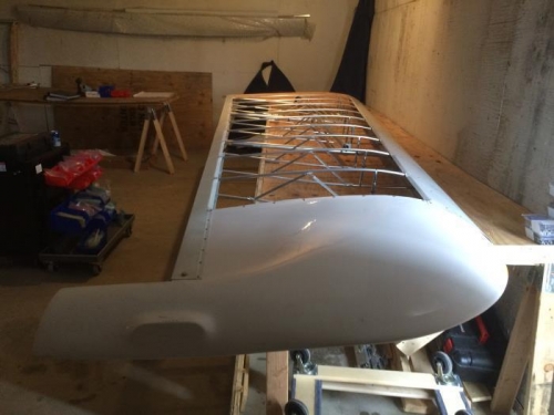
stbd wing frame ready for covering
|
|
|
|
|
|
|
|
|
Copyright © 2001-2024 Matronics. All Rights Reserved.
|