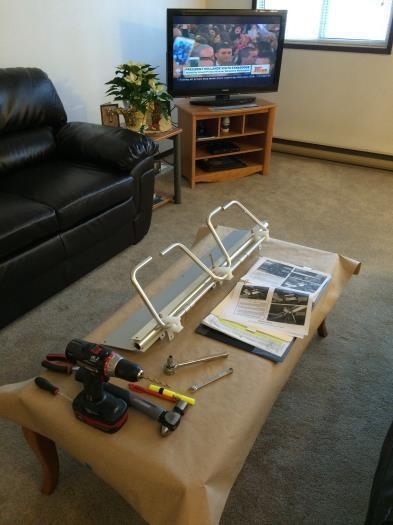
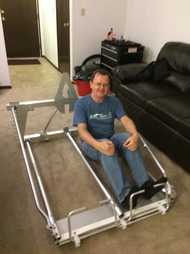
Got through most of the forward cockpit assemblies over three days. What a pain assembling the rudder pedal assembly was... like a Chinese puzzle! Finally got it, but then frustrating myself with the drilling for the Heel Rest Cap (step 2.1). What I learned from this was to do as little measuring as possible, instead use existing holes in the mating parts as templates and mark or directly drill through them. Step 4.2 calls for a AN4-10A bolt on the co-pilot side to secure the Cockpit Tube Upper LS to the Forward Cockpit Angle without explaining why since on the mirror image pilot side you use an AN4-07A bolt. The longer bolt can't be torqued up, must be something additional to attach here later? Got as far as step 7.2 before being stopped for lack of a pneumatic riveter again, as well as the last step 8. Moved the forward cockpit assembly in the back of my Ford Explorer with room to spare from the remote sub-assembly shop (my living room) to the main factory assembly hall (my hangar).
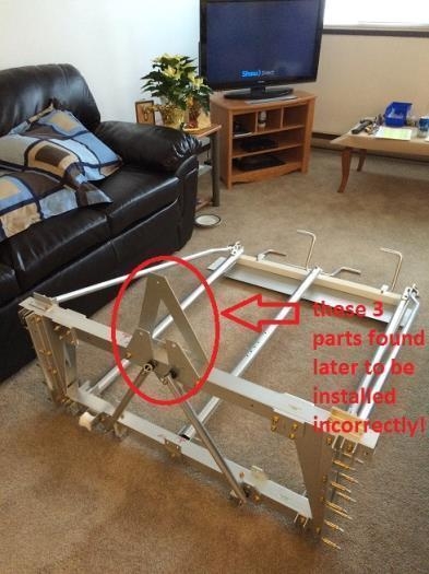
NOTE: Don't be like me and not heed the warning in Section 1 step 10 about the orientation of the Bulkhead Pylon Gusset. Also don't install the Actuator Mount Plates in Section 16 upside down... how did I ever do this?
Update 25 Oct 2015: The AN4-10A bolt, as observed at the PA factory and described in the new LSA manual Chapter 1 Section 1.2 page 3, is also used for securing the ground wire.