Brief Description: Attach Trim Servo Assembly to Tail Cone
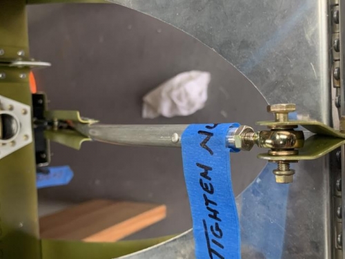
Guided the rod end bearing of the Trim/Servo Assembly up between the stabilator main skins to the AST Assembly control horns per figure 2 page 11iS/U-08.
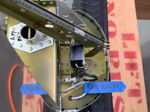
Installed the F-1287A-1 Servo Tray to the F-1211D Attach Brackets using one each AN3-35,NAS1149F0363P, AN310-3, and MS24665-151.
Temporarily installed the rod end bearing to the AST Assemblies using 1 AN3-10A, 3 NAS1149F0363P, and 1 MS21042-3 per figure 2 same page.
Connected 9 volt battery positive to the black wire and white wire to the negative to fully extend the servo shaft and disconnected battery.
Verified stabilator assembly movement to ensure it swings freely. Travel in both directions was limited only by the stabilator hinge stops contacting the F-1211C tailcone hinge bracket.
Connected 9 volt battery positive to the white wire and black wire to the negative to fully retract the servo shaft and disconnected battery.
Repeated the verification of stabilator movement.
Sealed all openings on the wire insertion side of the servo's D-Sub using RTV and plugged the connector on the end of the WH-P30-1 Trim wires into the connector on the wires coming from the ES MSTS-B6-7T-165 Pitch Trim Servo. Installed using 2 each MSM35206-218, ES-00164, and MS21042-04 and two tie wraps creating a relief at the top of the WH-P30-1 Trim Wire as shown in the call out figure 2 page 11iS/U-09