
|

|
|
|
Michaels Web Site
|
Date: 8-8-2011
|
Number of Hours: 2.75
|
Manual Reference:
|
Brief Description: F24-01 Cross Tie Box Ass'y
|
|
Made the F24-01 Cross Tie Box Assembly for the fuselage.
- Draw 5/32" offset line on legs of channels, per plans
- Clamp channel to work bench, standing up
- Clamp 2nd channel, 3" off of the first
- Align one face of cap strip along offset line of ONE channel
- Pilot drill and cleco in place
- Measure 3" wide at one end of the assembly, clamp, pilot drill and cleco one end hole.
- Move down the assembly with a ruler and measure a 3" wide assembly.
- Assume channel may not be perfectly straight and move down assembly, measuring 3" pilot drilling and cleco'ing as you go, until you reach the other end of the assembly
- Disassemble and debur
- I put in 6 clecos, turned the assembly over, LIGHTLY clamped it to the work bench, then did the same thing as above, for the other cap strip.
NOTE: PER THE DRAWINGS ONLY ONE CAP STRIP (the one with fewer holes) GETS RIVETED AT THIS TIME!
- Riveted one cap strip in place. More photos on the next page.
|
|
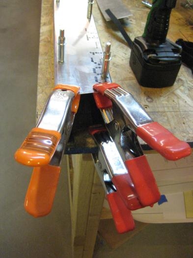
2 channels clamped to work bench at near end. Cap strip clamped on top.
|
|
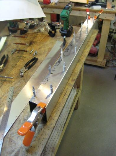
Overall view from opposite end.
|
|
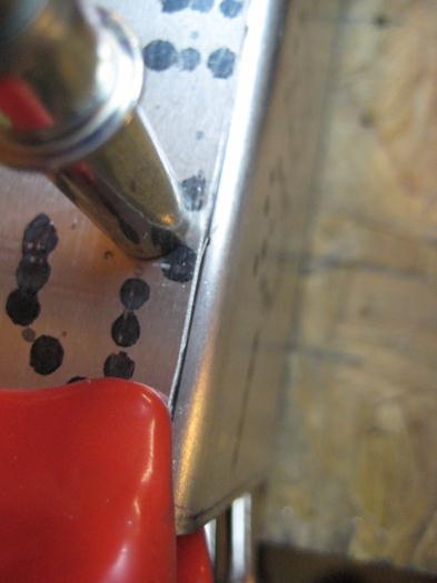
Align cap strip with offset line on channel. Pilot drill, cleco, measure 3" to the other face.
|
|
|
|
|
|
|
|
|
Copyright © 2001-2024 Matronics. All Rights Reserved.
|