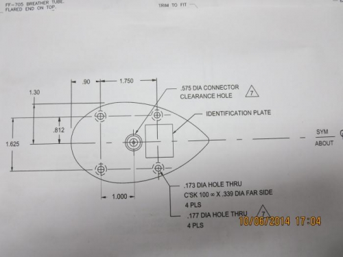
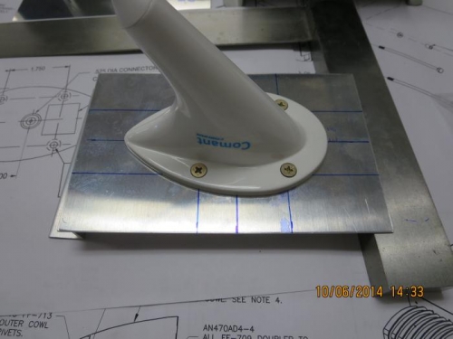
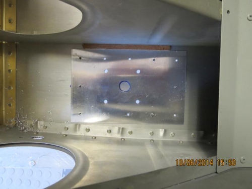
I received my 2 Comant CI-122 vhf antenna's from Stein Air last week and decided now was a good time to research and start on the antenna installation. Reviewing builder forums and builder websights and looking at my pictures from Oshkosh, I decided to mount both antenna's on the belly about 5" aft of the main wing spar. I also decided to reinforce the belly skin with an .032 piece of aluminum sheet measuring 4" x 6 1/4". I cut these on my bandsaw and deburred the edges. The Comant installation sheet shows the hole locations for the 4 mounting screws and the antenna connector. I transferred the measurements to the aluminum sheet and center punched the hole locations. I clamped the sheets together and drilled the screw locations to 11/64" and the antenna connector hole to 5/8". I also drilled 12 #40 holes around the perimeter for AN426AD3 rivets. I deburred all the holes. I marked the location on the fusalage belly skin just outside the last seat rib and 5" aft of the main wing spar. I used my 6" #40 drill bit and started to drill the rivet holes through the skin. I placed a cleco after each hole. I marked the connector hole using the reinforcing plate as a template. I removed the plate and used my step drill bit to bring the pilot hole to 5/8". I repeated the process for the left side. Next time I will dimple the skin and machine countersink the plates.